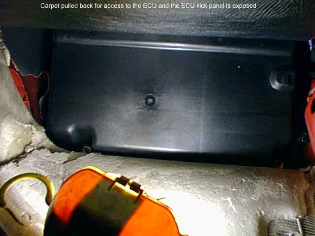
General information on the GReddy Boost Cut Controller (BCC)
When the turbo pressure sensor (TPS) of the Supra registers increasing boost pressure, it responds with an increased voltage to the ECU. If the standard pressure is exceeded, the TPS voltage signal causes the ECU to trigger the so-called Fuel Cut (FC) to prevent the boost pressure from increasing further.
The BCC is now simply switched between the TPS and the ECU, leaving the signal unaltered under normal pressure conditions, while at pressure above series the signal is held at the highest possible level BEFORE the FC.
This makes it possible to build up boost indefinitely without the ECU registering it. It should be remembered, however, that the amount of fuel always remains at the level of the highest standard pressure, so when pressure over series the risk of knocking and thus damaging the engine!
Note that GReddy does not officially produce BCC for the Supra JZA80 - instead the BCC of the '90 -'96 MR2 Turbo is used, part number: 15510006
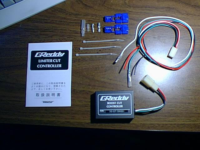
BCC wiring harness - declarations and notes
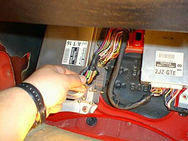
The TPS to the ECU has a black cable with two yellow stripes that goes into the larger ECU wiring harness!This cable is severed and the resulting end coming from the TPS is connected to the BCC's white input cable.
The other end, which goes to the ECU, is connected to the green output cable of the BCC.
Usually, the S / G cable is cut short behind the ECU.
It should be noted that the same cable can also be found in the harness top / rear in the engine. This variant, which is remote from the ECU, will be described in more detail below.
The red cable of the BCC can be connected to any ignition plus (12V).
It is therefore not necessary to use a cable of the ECU, although this would be possible.
Instead, one could use the unused seat-post security located in the top row of the fuse box on the left side of the driver's footwell.
The black cable of the BCC can be connected to any mass of the vehicle. Again, it is not necessary to use a cable from the ECU to ground the BCC.
Instead, you could crimp a ring to the cable and attach it to a body screw (remove paint).
- Red: Splice to wire marked 'B' on ECU diagram
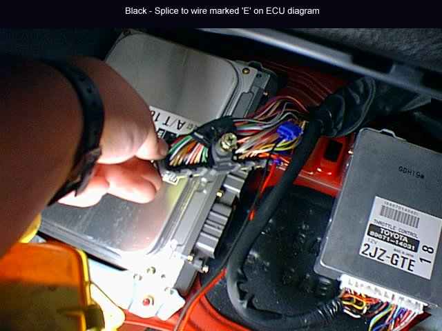
- Black_ Splice to wire marked 'E' on ECU diagram
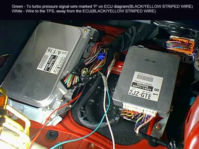
- Green: To turbo pressure signal wire marked 'P' on ECU diagram (BLACK / YELLOW STRIPED WIRE)
- White: Wire to the TPS, away from the ECU (BLACK / YELLOW STRIPED WIRE)
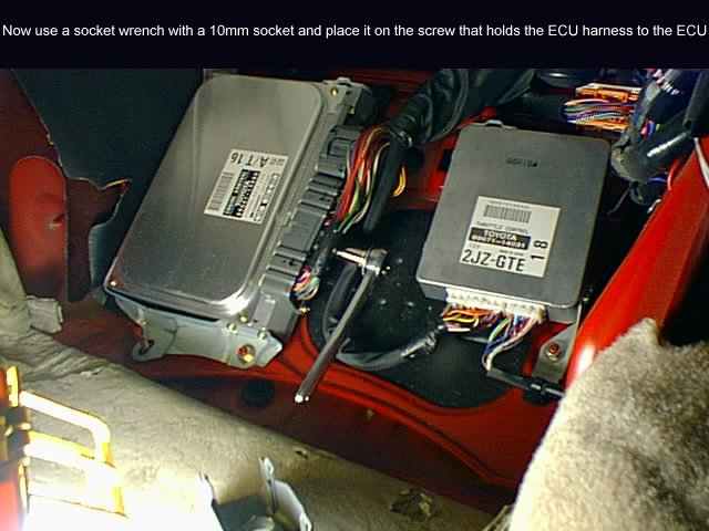
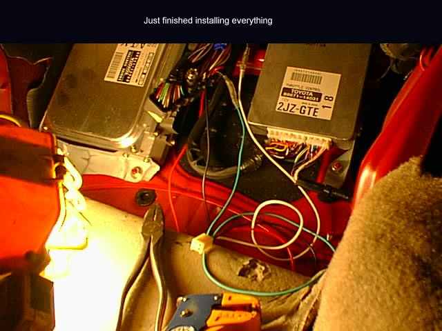
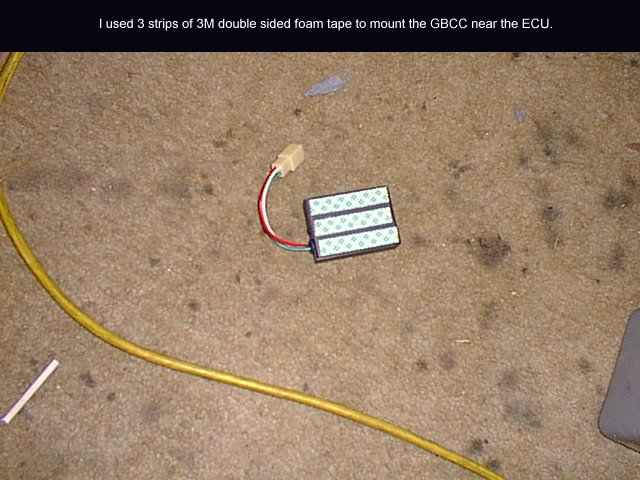
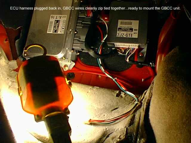
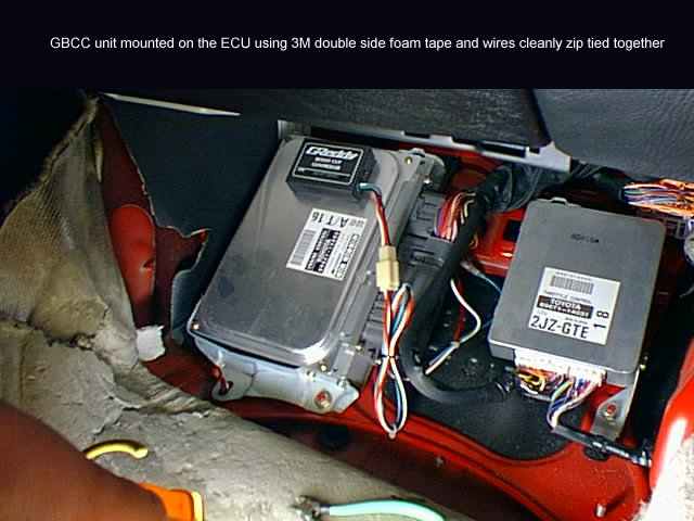
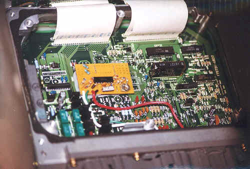
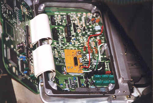
Once these connections are made, the BCC can be stowed somewhere near the ECU, behind the dashboard or fuse box. Some even put the BCC IN the ECU!
The Fields Harness Option:
This adapter is inserted between the plug / socket of the ECU wiring harness, allowing the connection of electronic devices without having to cut the original cables. Whether the purchase is worthwhile only for the BCC is questionable, because you only save the cutting of the black and yellow cable. In addition, the installation of the Fields Harness requires a repositioning of the Trac ECU.
Exact setting of the BCC output voltage
The BCC has a potentiometer for setting the peak output voltage. Since the ECU uses the TPS signal for many functions, this value should be just chosen so low that the FC is prevented and not deeper.
The default setting of GReddy works, but is lower than necessary and differs from part to part.
You can set the BCC pie times thumbs by driving the vehicle several times with maximum pressure while slowly adjusting the potentiometer counterclockwise until the FuelCut disappears.
However, this is a rather inaccurate and rough method, which is why we recommend setting with a voltmeter:
1. Adjusting the BCC voltage should be done when removed. When the BCC is fully installed, the green and white cables of the BCC must be disconnected, while the red and black can remain connected.
2. The red cable gets 12V voltage, eg. directly from the battery
3. The black cable gets ground, just like the negative sensor of the voltmeter (eg both to the battery)
4. The white cable to any voltage source of the vehicle between 5-12V. The easiest way to use the same as for the red cable. But even the 6V voltage of a charger would be conceivable, since any voltage between 5-12V to BCC cause the same output voltage for a particular adjustment of the potentiometer.
5. The green cable is connected to the positive sensor of the voltmeter
6. Now the potentiometer is set so that the voltmeter indicates near but not above: 4.3V for 93-95 supras and 4.1V for 96-98 supras.
Alternative connection of the BCC remote from the ECU
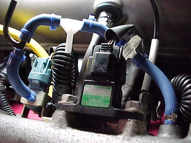 After identifying the turbo pressure sensor at the top of the intake manifold, you can see 3 cables. The middle one is the black with the two yellow stripes. Now you know what the "target cable" looks like and can remove the plastic cover from the large harness that runs up / down the splash guard wall. The mounting clips are difficult to remove, you should use two small screwdrivers and bring a lot of patience.
On the driver side of the now unprotected wiring harness you remove the insulating tape, so that the cables can be separated. Make sure that some colors like brown, beige, etc. can look very similar to yellow.
Therefore, a bright light should be used to accurately look at and distinguish each cable. There are two cables that combine black with yellow stripes, but one is definitely thicker.
The thinner cable is that we need for the BCC - you should compare it to that coming from the TPS.
Only if you are 100% sure to have the right cable, you should cut it. The decision can then be checked again by means of voltmeters by measuring the resistance between the two cable ends (it should be less infinite).
Now the cable end coming from the TPS is connected to the white cable of the BCC and the other end to the green cable.
The cable ends of the BCC should be led from the interior through the splash guard wall on the clutch pedal, more details in the TechArtikel for the installation of additional instruments.
Now the BCC cables are crimped to the severed cable ends and the entire cable harness is re-insulated and protected with the plastic cover.