Original Items & Images by mkivsupra.net
Translation: Bama Boy
If BPU TwinTurbo Supras are driven on the increased boost pressure with the series twins, an FCD is unavoidable with the production ECU!
What is a fuel cut anyway?
By means of a pressure sensor, the ECU (engine control unit) is informed continuously of the current boost pressure. If the boost pressure exceeds a certain value (about 1.0 bar), the ECU shuts off the fuel injectors to protect the engine (fuel cut). To still be able to drive a higher boost pressure, it is therefore necessary to deceive the ECU on the actual boost pressure. To do this, the Boost Cut Controller (Fuel Cut Defencer / FCD) is inserted between the pressure sensor and the ECU.
Let's go:
What do I need? HKS FCD (Set it to Pos 9). 10mm / 12mm NUT, cable clamps and a pair of pliers to insulate. The cable clamps can also be replaced by a soldering iron and heat shrink tubing.
First, the battery is disconnected once to avoid short circuits.
Now it goes to the passenger footwell. You take out the doormat and pull the carpet aside until you see a large plastic panel in the footwell. Under this cover is the engine control unit. Remove the panel by removing the two 10mm screws.
Here you can see the cover
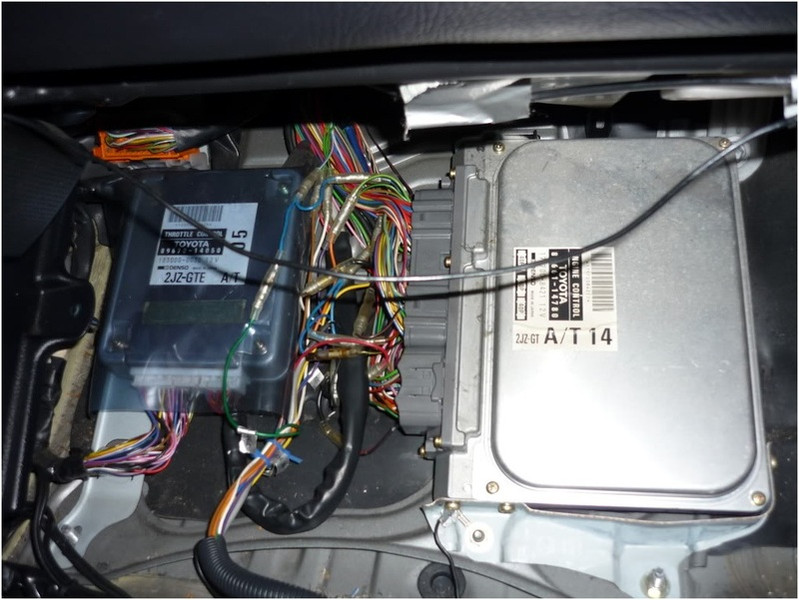
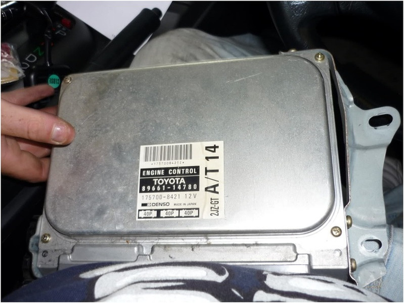
So it looks like when the cover is out. The connectors to the engine control unit must be removed
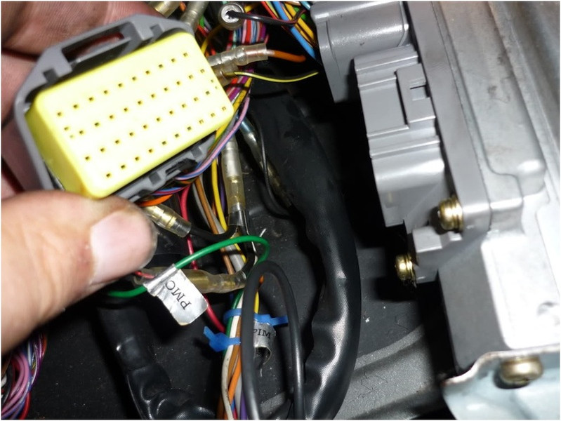
One of the three plugs can be easily removed - as seen here
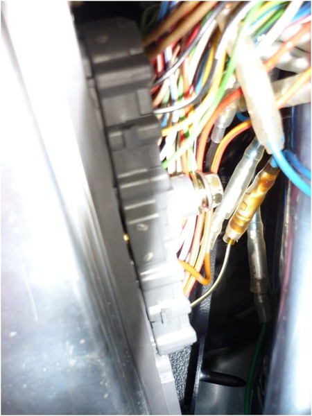
The other two plugs are secured by a 10mm nut. Removes the screw between the two plugs to pull off these
The controller now has no contacts to the three plugs and you can just take it out after you have the fixing screw / n solved by the controller
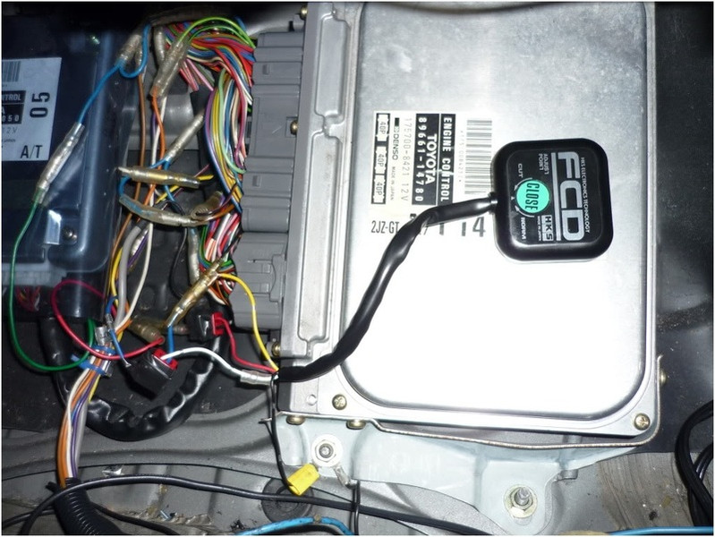
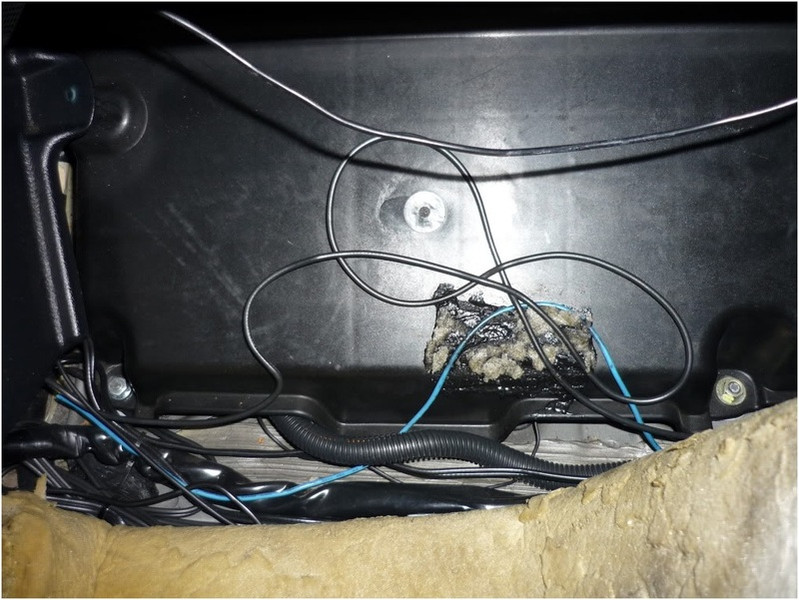
In this photo you can see the earth cable attached to the body at the bottom of the picture. Bring the FCD down safely (best you can attach the second control unit (right next to the engine control unit) in the footwell with double-sided tape) - Not as in this photo on the engine control unit but as I said on the left side of the control unit
cabling
 Now it's time for the fun part - diligently search out the cables that are needed - take your time making sure you've found the right cable. An error and a wrongly clamped / soldered cable have fatal consequences!
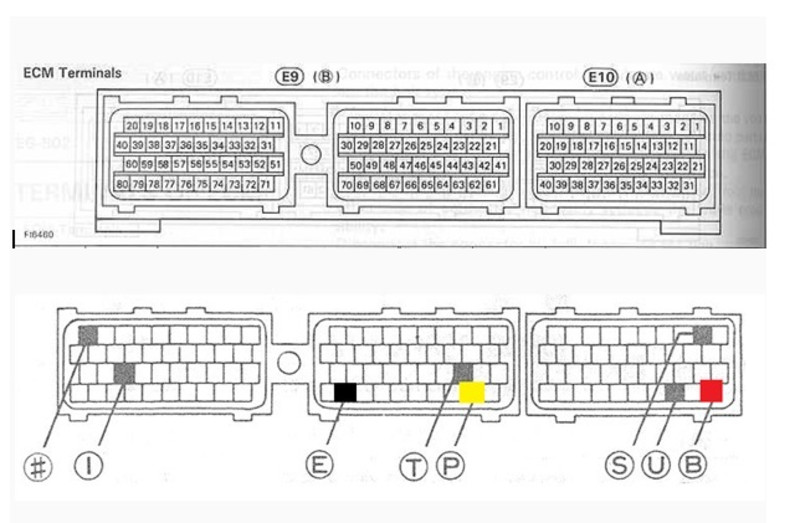
- Red cable l - Connect this cable (+) to "B". (Pin 31)
- Black cable - Connect this cable (ground / -) to "E". (Pin 69) OR connect to the body later. (there is another picture)
- Yellow cable - Connect this cable (pressure sensor) to "P" (control unit side). (Pin 62)
- White cable - Connect this cable (pressure sensor) to "P" (harness side).
Well, maybe some people wonder how the yellow and the white cable are connected correctly. Quite simple: The cable on pin 62 is cut short before the plug (remaining 5-10 cm remaining cable) COMPLETE. Now, the yellow wire from the FCD is connected to the cable end to the controller side / connector side. The white cable is connected to the other end of the severed cable (harness side).
As I said, you can either connect the cables with cable clamps or with the soldering iron - I preferred to do these steps with the soldering iron! Do not forget to isolate sensibly!
If all the cables are connected you can re-install the ECU and reconnect the 3 plugs (do not forget the 10 MM nut!)
finish
Now you rebuild everything (plastic cover / carpet / doormat) and reconnect the battery to the vehicle. Take a good look at the plastic cover - it has a longer hook that gives it stability, this can get stuck with a bit of bad luck on the newly connected cable and pull it out. Start the engine and do not be surprised if the idle running is a bit quiet or too high - the engine control unit takes a few minutes to learn the idle again properly.
It works - tests if everything works fine - if you can keep a charge pressure of eg 1.2 bar stable without slamming almost through the windscreen after a short time you have done everything right