


- Introduction
- Maintenance
- Preparation
- Service specifications
- Diagnostics
- 2JZ-GE Engine
- 2JZ-GTE Engine
- 2JZ-GTE Turbocharging
- 2JZ-GE Emission control
- 2JZ-GTE Emission control
- 2JZ-GE SFI
- 2JZ-GTE SFI
- Cooling
- Lubrication
- Ignition system 2JZ-GE
- Ignition system 2JZ-GTE
- Starting system
- Charging system
- Clutch
- W58 manual transmission
- V160 manual transmission
- A340E 2JZ-GE automatic transmission
- A340E 2JZ-GTE automatic transmission
- Propeller shaft
- Suspension and axle
- Brake system
- Steering
- Supplemental restraint system
- Body electrical system
- Body
- Air conditioning system
- A/T:
Check torque converter clutch installation
Using calipers and straight edge, measure from the installed surface of the torque converter clutch to the front surface of the transmission.
Correct distance: Less than 0.1 mm (0.004 in.)
If the distance is not as specified, check for an improper installation.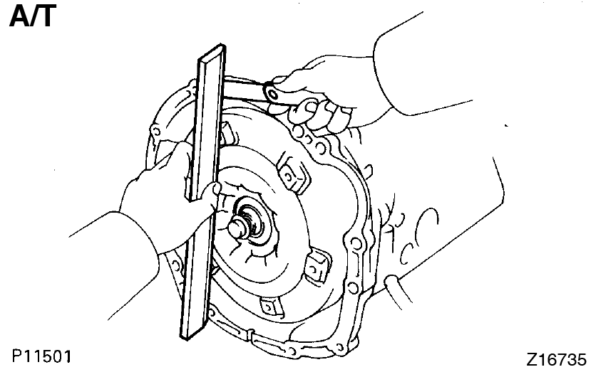
- Assemble engine and transmission
- M/T:
Align the input spline with the clutch disc and install the transmission to the engine. - Align the 2 knock pins on the cylinder block with the pin holes of the clutch housing.
- Install the transmission with the 6 bolts.
Torque:
14 mm head 39 N·m (400 kgf·cm, 29 ft·lbf)
17 mm head 72 N·m (730 kgf·cm, 43 ft·lbf)

- M/T:
- M/T:
Install clutch cover set bolts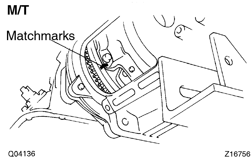
- Align the matchmarks.
- Install the 6 bolts while turning the crankshaft to gain access. Tighten the bolts evenly.
Torque: 19 N·m (195 kgf·cm, 14 ft·lbf) - Install the service hole cover with the 2 bolts.
Torque: 12 N·m (120 kgf·cm, 9 ft·lbf)
- A/T:
Install torque converter clutch mounting bolts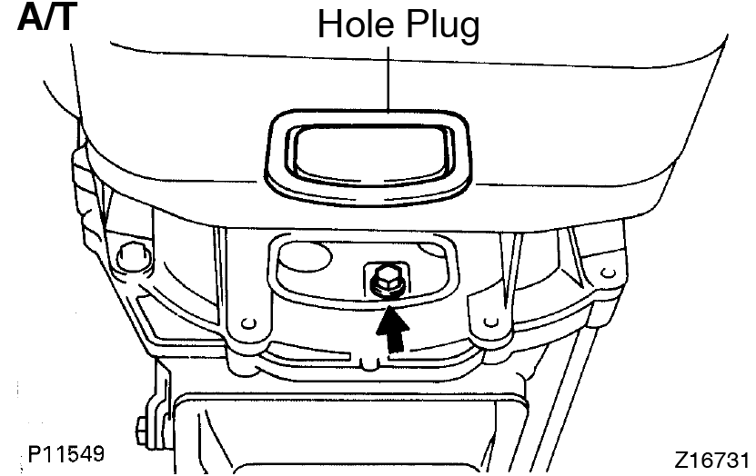
- First, install the gray bolt. Then install 5 black bolts while turning the crankshaft to gain access. Tighten the bolts evenly.
Torque: 33 N·m (340 kgf·cm, 25 ft·lbf) - Install the hole plug.
- First, install the gray bolt. Then install 5 black bolts while turning the crankshaft to gain access. Tighten the bolts evenly.
- A/T:
Install oil cooler pipe for transmission- Temporarily install the 2 oil cooler pipe, 2 hose clamps and tube clamp with 3 clamp bolts.
- Connect the 2 oil cooler tubes to the unions on the transmission. Tighten the union nuts.
Torque:44 N·m (450 kgf·cm, 33 ft·lbf) - Tighten the 3 clamp bolts.
- Install starter
- Connect engine wire to transmission
- A/T:
Install oil dipstick and guide for transmission- Install a new O-ring to the dipstick guide.
- Connect the dipstick guide end to the dipstick tube of the oil pan.
- Install the dipstick guide with the bolt.
- Install the dipstick.
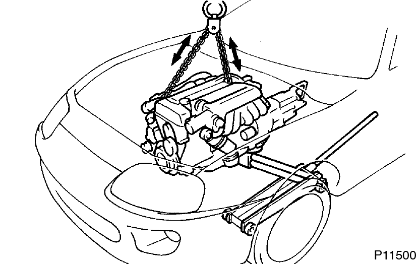
- Install engine and transmission assembly in vehicle
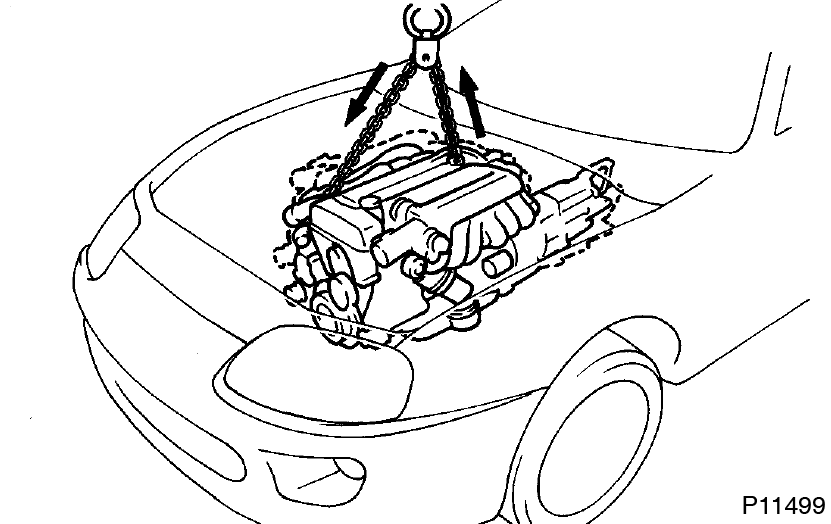
- Attach the engine hoist chain to the engine hangers.
- Lower the engine and transmission assembly into the engine compartment. Install the engine and transmission assembly carefully without damaging the shift lever retainer (M/T), A/C compressor and PS solenoid valve.
- Insert the stud bolts of the front engine mounting insulators into the stud bolt holes of the front suspension crossmember.
- Temporarily install the 2 nuts holding the engine front mounting insulators to the front suspension crossmember.
- Keep the engine level with a jack.
- Remove the hoist chain.
- Temporarily install the support member to the engine rear mounting insulator with the 4 nuts.
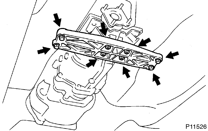
- Install the 4 bolts holding the support member to the body.
Torque: 25.5 N·m (260 kgf·cm, 19 ft·lbf) - Tighten the 4 nuts holding the support member to the engine rear mounting insulator.
Torque: 13 N·m (135 kgf·cm, 10 ft·lbf) - Tighten the 2 nuts holding the engine front mounting insulators to the front suspension crossmember.
Torque: 59 N·m (600 kgf·cm, 43 ft·lbf)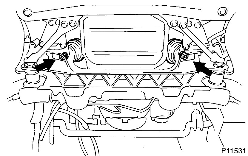
- M/T:
Install transmission shift lever
Torque: 19 N·m (195 kgf·cm, 14 ft·lbf) - A/T:
Connect transmission control rod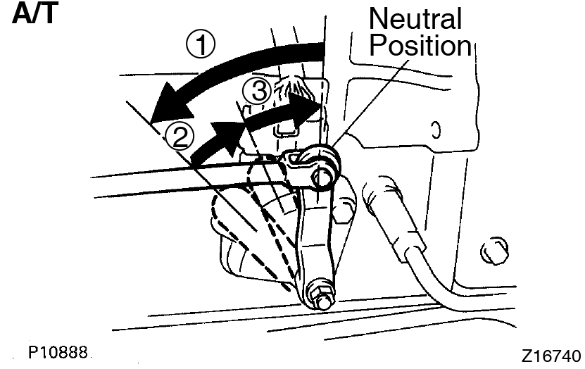
- Shift the shift lever to N position.
- Fully turn the control shaft lever back and return 2 notches. It is now in neutral position.
- Connect the control rod to the shift lever with the nut.
Torque: 13 N·m (130 kgf·cm, 9 ft·lbf)
- Install propeller shaft (See page PR-11)
- Install rear center floor crossmember brace
Torque: 28 N·m (290 kgf·cm, 21 ft·lbf) - Install exhaust pipe heat insulator
- Install No.2 front exhaust pipe
Install a new gasket and the front exhaust pipe with 3 new nuts.
Torque: 62 N·m (630 kgf·cm, 46 ft·lbf) - Install exhaust pipe assembly
- Install the hook of the tailpipe to the 2 rings on the tailpipe bracket.
- Install the hook of the exhaust pipe to the 2 rings on the exhaust pipe brackets.
- Install the pipe support bracket with the 2 bolts.
Torque: 43 N·m (440 kgf·cm, 32 ft·lbf) - Install a new gasket and the No.2 front exhaust pipe to the front exhaust pipe with the 2 bolts and 2 new nuts.
Torque: 58 N·m (590 kgf·cm, 43 ft·lbf)
- Install heated oxygen sensor
Install a new gasket, the oxygen sensor and sensor cover with the 2 nuts.
Torque: 20 N·m (200 kgf·cm, 14 ft·lbf) - M/T:
Install clutch release cylinder and ground strap- Install the clutch release cylinder with the 2 bolts.
Torque: 13 N·m (130 kgf·cm, 9 ft·lbf) - Connect the clutch line tube with the bolt.
Torque: 37 N·m (380 kgf·cm, 27 ft·lbf) - Install the ground strap with the bolt.
Torque: 37 N·m (380 kgf·cm, 27 ft·lbf)
- Install the clutch release cylinder with the 2 bolts.
- Connect engine wire to cabin
- Push in the engine wire through the cowl panel. Be careful not to damage the engine wire.
- Connect the 2 connectors to the connector cassette.
- Connect the connector to the instrument panel wire connector.
- Connect the 2 connectors to the ECM.
- Connect the connector to the TRAC ECU.
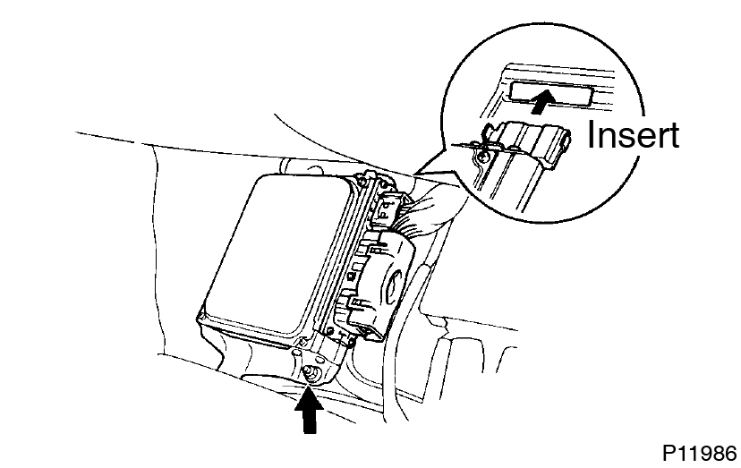
- Insert the ECM bracket into the stay on the floor panel.
- Install the ECM with the nut.
- Install the ECM protector with the 2 nuts.
- Install the floor carpet.
- Install the scuff plate.
- Push in the engine wire through the cowl panel.
- M/T:
Install upper console panel, shift lever boots and holding bolts - Connect engine wire to cowl panel
- Install A/C compressor
- Using a torx socket (E10), install the stud bolt and compressor.
Torque: 26 N·m (265 kgf·cm, 19 ft·lbf) - Connect the compressor connector.
- Temporarily install the compressor with nut and 3 bolts.
- Alternately tighten the bolt and nut.
Torque: 52 N·m (530 kgf·cm, 38 ft·lbf)
- Using a torx socket (E10), install the stud bolt and compressor.
- Install PS pressure feed hose
Install the pressure feed hose with the 2 clamp bolts. - Install PS pump
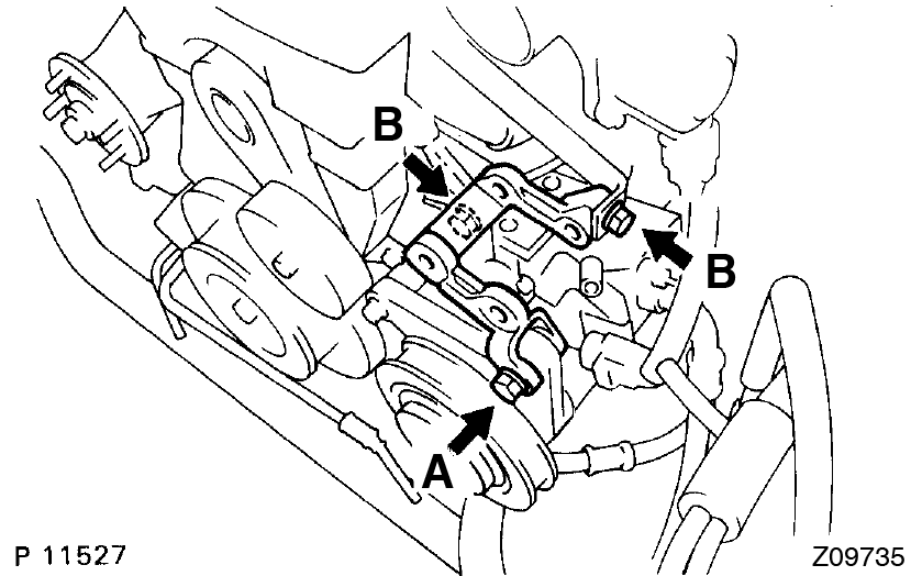
- Install the pump bracket with the 3 bolts.
Torque:- 58 N·m (590 kgf·cm, 43 ft·lbf)
- 39 N·m (400 kgf·cm, 29 ft·lbf)
- Install the vane pump with the 2 bolts.
Torque: 58 N·m (590 kgf·cm, 43 ft·lbf) - Connect these hoses:
- PS air hose to throttle body
- PS air hose to air intake chamber
- Install the pump bracket with the 3 bolts.
- Connect fuel hoses
- Connect the fuel return hose to the fuel return pipe.
- Install the fuel return hose to the clamp of the dipstick guide.
- Install the fuel inlet hose with 2 new gaskets and the union bolt.
Torque: 29 N·m (300 kgf·cm, 22 ft·lbf)
- Connect wires and connectors
- Connect evap hose
- Connect brake booster vacuum hose
- Connect heater water hoses
- Install charcoal canister
- Install water pump pulley, fan, fluid coupling assembly and drive belt (See page CO-11)
- M/T:
Install drive belt tensioner damper (See page EM-21 ) - Install air cleaner and MAF meter assembly
- Install No.1 air hose
- Connect control cables to throttle body
- Fill with engine oil
- Install radiator assembly (See page CO-28 )
- Start engine and check for leaks
- Install hood
- Road test
Check for abnormal noise, shock slippage, correct shift points and smooth operation. - Recheck engine coolant and engine oil levels
This guide is based on the book edition Toyota (RM502U, 1997)