


- Introduction
- Maintenance
- Preparation
- Service specifications
- Diagnostics
- 2JZ-GE Engine
- 2JZ-GTE Engine
- 2JZ-GTE Turbocharging
- 2JZ-GE Emission control
- 2JZ-GTE Emission control
- 2JZ-GE SFI
- 2JZ-GTE SFI
- Cooling
- Lubrication
- Ignition system 2JZ-GE
- Ignition system 2JZ-GTE
- Starting system
- Charging system
- Clutch
- W58 manual transmission
- V160 manual transmission
- A340E 2JZ-GE automatic transmission
- A340E 2JZ-GTE automatic transmission
- Propeller shaft
- Suspension and axle
- Brake system
- Steering
- Supplemental restraint system
- Body electrical system
- Body
- Air conditioning system
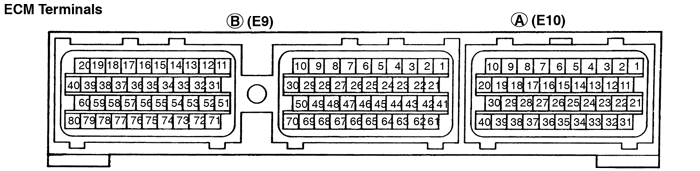
Connectors of the ECM are water-proof and are the bolt type. For water proof type connectors, in order to measure the voltage of ECM terminals and the resistance of connected parts, connect the inspection check harness between the ECM and vehicle wire harness, then perform the inspection.
The inspection method of inserting a tester probe from the other side of connector noticeably reduces the water-proof ability.
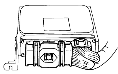
Disconnect the connector by fully loosening the bolt.
- Turn the ignition switch to LOCK position.
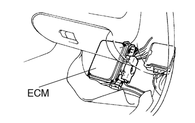
- Turn up the passenger side floor mat.
- Remove the ECM protector.
- Disconnect the connectors from the ECM.
After completely loosening the bolt, the 2 parts of connec- tor can be separated.- Do not pully the wire harness when disconnecting the connector.
-
 When disconnecting the connector, the ECM’s backup power source is cut off, so the DTC, etc. recorded in the ECM memory are cancelled.
 - Never insert a tester probe or male terminal used for inspection purposes into the female terminal of the vehicle wire harness. Otherwise, the female terminal may be widened, which can result in faulty connection.
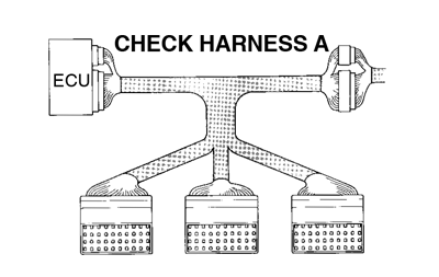
- Connect the Check Harness A between ECM and con- nector of vehicle wire harness
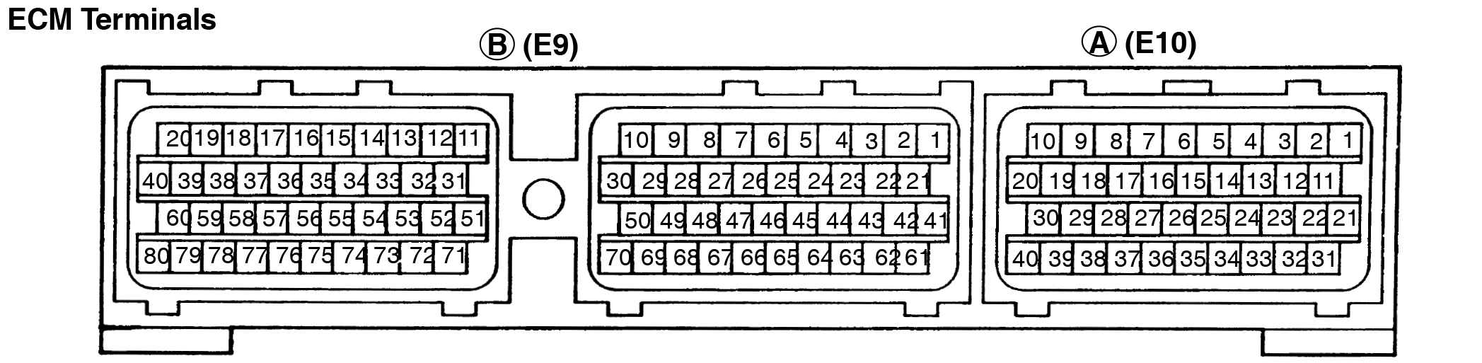
SST 09990-01000The arrangement of the DLC1 terminals are the same as those of the ECM (See page DI-20).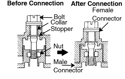
- Disconnect the Check Harness A.
- Reconnect the connectors to the ECM.
- Match the male connector correctly with female connector, then press them together.
- Tighten the bolt.
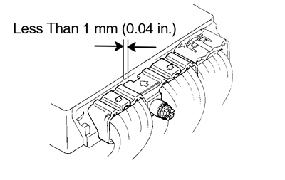
Make sure the connector is completely connected, by tightening the bolt until there is a clearance of less than 1 mm (0.04 in.) between bottom of the male connector and end of the female connector.
- Install the ECM protector and floor mat.
| Symbols (Terminals No.) | Wiring Color | Condition | STD Voltage (V) |
| BATT (A33) - E1 (B69) | B-W ↔ BR | Always | 9 - 14 |
| IGSW (A1) - E1 (B69) | B-W ↔ BR | IG switch ON | 9 - 14 |
| +B (A31) - E1 (B69) | B-R ↔ BR | IG switch ON | 9 - 14 |
| VC (B41) - E2 (B65) | L-R ↔ W-B | IG switch ON | 4.5 - 5.5 |
| IDL1 (B64) - E2 (B65) | R-B ↔ W-B | IG switch ON and apply vacuum to the throttle opener Throttle valve fully closed | -0.1 - 3.0 |
| IG switch ON Throttle valve fully opened | 9 - 14 | ||
| VTA1 (B43) - E2 (B65) | Y ↔ W-B | IG switch ON Throttle valve fully closed | 0.3 - 0.8 |
| IG switch ON Throttle valve fully opened | 3.2 - 4.9 | ||
| VG (B66) - EVG (B28) | Y-R ↔ BR | Idling, P or N Position, A/C switch OFF | 0.7 - 1.7 |
| THA (B45) - E2 (B65) | P-L ↔ W-B | Idling, Intake air temp. 0°C (32°F) to 80°C (176°F) | 0.5 - 3.4 |
| THW (B44) - E2 (B65) | L-Y ↔ W-B | Idling, Engine Coolant temp. 60°C (140°F) to 120°C (248°F) | 0.2 - 1.0 |
| STA (B77) - E1 (B69) | B ↔ BR | Cranking | 6.0 or more |
| #10 (B20) - E01 (B80) | R-L ↔ BR | IG switch ON | 6.0 or more |
| Idling | Pulse generation (See page DI-60) | ||
| #20 (B19) - E01 (B80) | R-Y ↔ BR | IG switch ON | 6.0 or more |
| Idling | Pulse generation (See page DI-60) | ||
| #30 (B18) - E01 (B80) | R-G ↔ BR | IG switch ON | 6.0 or more |
| Idling | Pulse generation (See page DI-60 ) | ||
| #40 (B17) - E01 (B80) | R-W ↔ BR | IG switch ON | 6.0 or more |
| Idling | Pulse generation (See page DI-60 ) | ||
| #50 (B16) - E01 (B80) | R ↔ BR | IG switch ON | 6.0 or more |
| Idling | Pulse generation (See page DI-60) | ||
| #60 (B15) - E01 (B80) | R-B ↔ BR | IG switch ON | 6.0 or more |
| Idling | Pulse generation (See page DI-60 ) | ||
| IGT (B57) - E1 (B69) | R-W ↔ BR | Idling | Pulse generation (See page DI-115) |
| IGF (B58) - E1 (B69) | R-Y ↔ BR | IG switch ON | 4.5 ∼ 5.0 |
| Idling | Pulse generation (See page DI-115) | ||
| G1 (B26) - G≥ (B7) | R ↔ G | Idling | Pulse generation (See page DI-65 ) |
| G2 (B25) - G≥ (B7) | W ↔ G | Idling | Pulse generation (See page DI-65 ) |
| NE (B27) - G≥ (B7) | B ↔ G | Idling | Pulse generation (See page DI-65 ) |
| NE2 (B4) - NE2≥ (B5) | B ↔ W | Idling | Pulse generation (See page DI-65 ) |
| M-REL (A24) - E1 (B69) | B-Y ↔ BR | IG switch ON | 9 - 14 |
| FPC (A22) - E1 (B69) | V-W ↔ BR | IG switch ON | Below 0.5 |
| Idling | Pulse generation (0 and 4.0 ∼ 5.5) | ||
| DI (A21) - E1 (B69) | G ↔ BR | Idling | 7.0 or more |
| ACIS (B39) - E01 (B80) | G-Y ↔ BR | IG switch ON | 9 - 14 |
| EVAP (B74) - E01 (B80) | V ↔ BR | IG switch ON | 9 - 14 |
| EGR (B75) - E01 (B80) | P ↔ BR | Idling | Below 2.0 |
| Engine speed at 3,500 rpm | 9 - 14 | ||
| ISC1 (B35) - E01 (B80) | Y-B ↔ BR | Idling, When A/C Switch ON or OFF | Pulse generation (See page DI-103 ) |
| ISC2 (B34) - E01 (B80) | G-W ↔ BR | Idling, When A/C Switch ON or OFF | Pulse generation (See page DI-103 ) |
| ISC3 (B33) - E01 (B80) | L-B ↔ BR | Idling, When A/C Switch ON or OFF | Pulse generation (See page DI-103 ) |
| ISC4 (B32) - E01 (B80) | R-B ↔ BR | Idling, When A/C Switch ON or OFF | Pulse generation (See page DI-103 ) |
| OX1 (B48) - E1 (B69) | W ↔ BR | Maintain engine speed at 2,500 rpm for 2 min. after warning up | Pulse generation (See page DI-93 ) |
| OX2 (B47) - E1 (B69) | R-L ↔ BR | Maintain engine speed at 2,500 rpm for 2 min. after warning up | Pulse generation (See page DI-93 ) |
| OX3 (A30) - E1 (B69) | R-L ↔ BR | Maintain engine speed at 2,500 rpm for 2 min. after warning up | Pulse generation (See page DI-93 ) |
| HT1 (B71) - E01 (B80) | G ↔ BR | Idling after warning up | Below 3.0 |
| IG switch ON | 9 - 14 | ||
| HT2 (B72) - E01 (B80) | B-Y ↔ BR | Idling after warning up | Below 3.0 |
| IG switch ON | 9 - 14 | ||
| HT3 (A36) - E01 (B80) | BR-W ↔ BR | Idling after warning up | Below 3.0 |
| IG switch ON | 9 - 14 | ||
| KNK1 (B50) - E1 (B69) | W ↔ BR | Idling | Pulse generation (See page DI-65 ) |
| KNK2 (B49) - E1 (B69) | W ↔ BR | Idling | Pulse generation (See page DI-65 ) |
| NSW (B76) - E1 (B69) | B-W ↔ BR | IG switch ON Other shift position ”P” or ”N” position | 9 - 14 |
| IG switch ON Shift position in ”P” or ”N” position | -0.1 - 3.0 | ||
| SP1 (A2) - E1 (B69) | P ↔ BR | IG switch ON Rotate driving wheel slowly | Pulse generation (See page DI-100 ) |
| TE1 (A20) - E1 (B69) | Y-L ↔ BR | IG switch ON | 9 - 14 |
| W (A6) - E1 (B69) | L-B ↔ BR | Idling | 9 - 14 |
| IG switch ON | -0.1 - 3.0 | ||
| OD1 (A12) - E1 (B69) | BR-B ↔ BR | IG switch ON | 9 - 14 |
| AC (A34) - E1 (B69) | L-R ↔ BR | A/C switch ON (At idling) | -0.1 - 1.5 |
| A/C switch OFF | 9 - 14 | ||
| ACMG (A23) - E01 (B80) | W-G ↔ BR | A/C switch ON (At idling) | -0.1 - 3.0 |
| A/C switch OFF | 9 - 14 | ||
| FPU (B73) - E01 (B80) | W-L ↔ BR | IG switch ON | 9 - 14 |
| Restarting at high engine coolant temp. | Below 2.0 | ||
| ELS (A15) - E1 (B69) | R-Y ↔ BR | Defogger switch and taillight switch ON | 7.5 - 14 |
| Defogger switch and taillight switch OFF | -0.1 - 1.5 | ||
| SDL (A8) - E1 (B69) | G ↔ BR | During transmission | Pulse generation |
This guide is based on the book edition Toyota (RM502U, 1997)